
Output Devices (Servo Driver Board)
this weeks Assignment is to build an outpt device a device that can take data from the vitual world and outout physicaly in the real world this can take meny forms Light's Sound etc but i chose mechanical using servo motors to be exact and thus tought towards my final project whish has 2 servo drivine robotic arms and thus controlling 10 servos would be hard with only one MCU and thus i though of spliting them into 2 seprate boards communicating to a main CPU over I2C and thus all the elemnts where in place and the Goal Was set
Project: I2C Robotic Arm Controller
Goal: Design and Fabricate a servo Controller that control up to 6 RC PPM Servo Motors
Files Used In this Project can be Downloaded here
Let the Dance Begin !!!
1st of all taking a look at the fab Academy boards at the servo board i found after milling it that the regulator gets hot after a while and there was only 2 servo ports also it used a ATtiny 44 which has an 8bit timer and to use servos you need a 16bit timer or at least thats what i was told unless you do a software PWM (Timer) as to incress the number of servos used
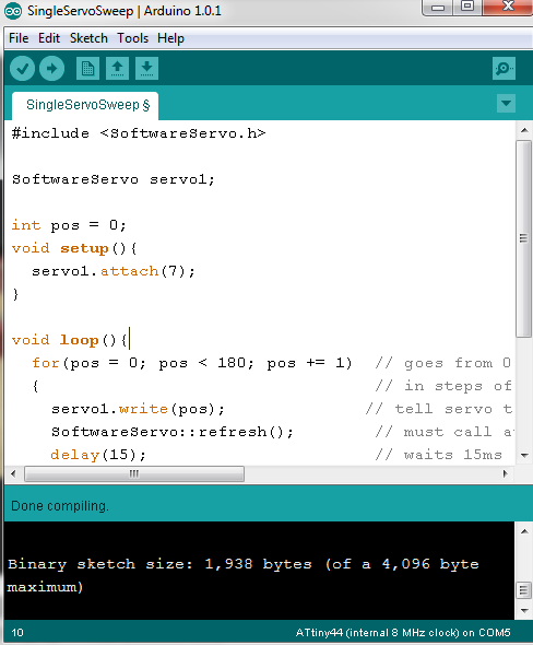
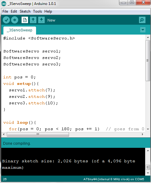
so i started the design prosess with arduinos software servo library in mind
but 1st i had to test all the concepts 1st was the servo and Software servo library so going back to my input device Assignment the SOIc14 Breakout board was helfull in testing out the software servo library
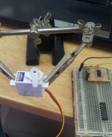
It works it jurkes somtimes but after a of playing around with the power supplay i got it to a useable state
and now designing the pcb process a lot like The input devices design process w/abit more deckin out
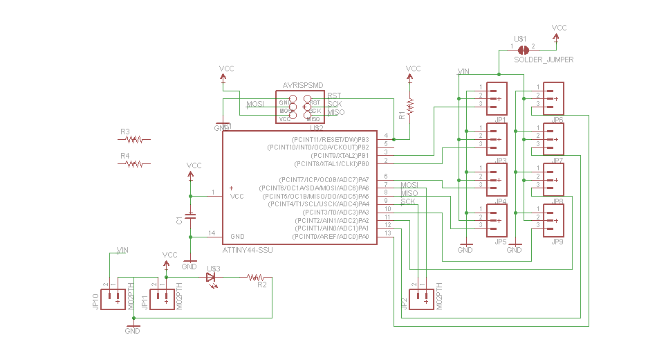
The board are almost excatly a like but with a few exptions such as the dual Power Inputs and the selctor jumper and of cource the diffrent servo pinout
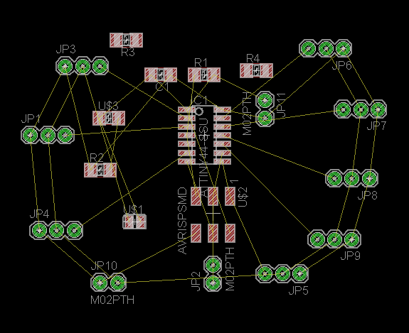
and now the Layout i have a love hate relation ship with PCB Layout i am slowly getting better at it but still i have a long way to go
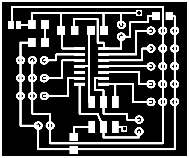
but after a bit of trail and error and using eagles built in tools i went from this
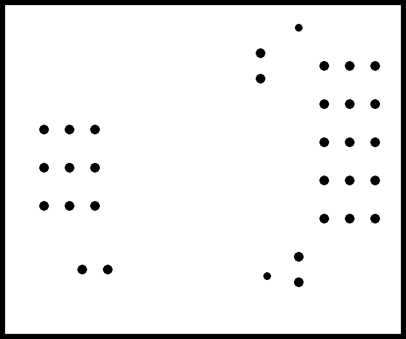
to this
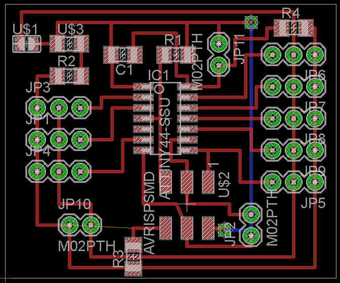
Easy And Pain less NOT!!!!
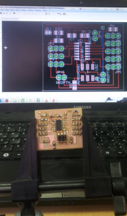
and No comes a bit of GIMP work and we are on with a working set of files
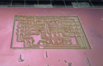
and We are of milling Drilling and Cutting the PCB
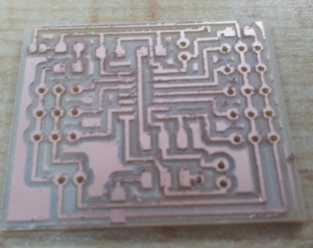
and Now after a bit of soldring we get this baby
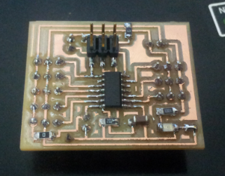
and now for the test of truthe : avrdude -c usbtiny -P usb -p t44

Another Sucsess !!!!!!!!!!!!
Awsome now comes testing
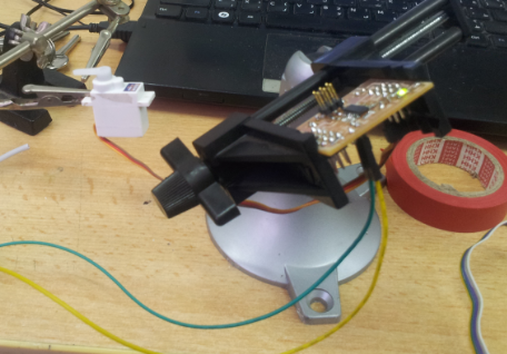
And a Sucsess Single Servo Checks Out
Now For 3 Servos (2 Showen)
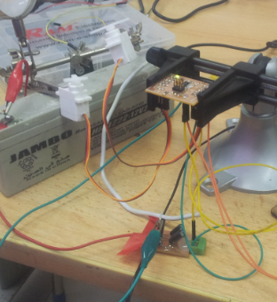
Another Sucsses but w/ a bit of servo jitter so will look into that it might need a bit of smoothing on the signal line but for now this is good enogh for testing the application
Next Step will be emplemnting the I2C bus and having it communicate with the main CPU to get kinimatic data on where to turn each servo to get the end effector to its desired location
Awesome See you Next Week